This section provides an introduction to openBIM in terms of data formats used, services available and associated methodologies. This includes the IFC data structure, the bSDD platform, the IDM methodology, MVD, IDS, software certification, the buildingSMART Validation Service, BCF comments and DataSheets.
IFC data structure
IFC is the abbreviation for Industry Foundation Classes. It is an open data format (data schema) for building information. It is based on the STEP Physical File (SPF, STEP = Standard for the Exchange of Product model data). Another data format is XML. Since 1995, buildingSMART international has been developing IFC as part of the openBIM standard. Since 2013 (publication of IFC4), IFC has been an official ISO standard with ISO 16739 and is regularly updated with this standard (since 2018: ISO 16739-1). buildingSMART also recommends IFC for referencing and archiving models.
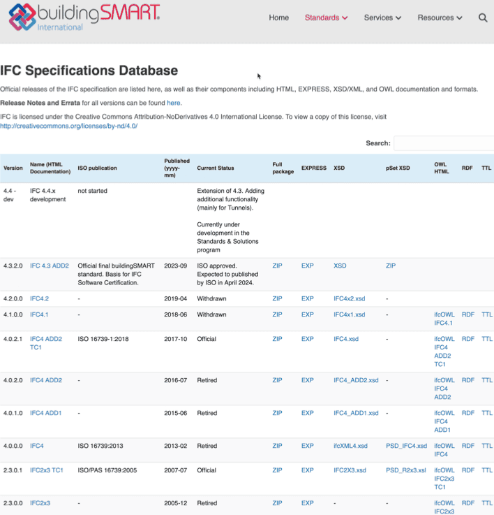
With the IFC4 version, all essential building construction trades can be mapped in the data structure. Version IFC4.3, which will be ISO-certified in spring 2024, enables the integration of the infrastructure areas of road, rail, bridge, tunnel and the associated routing (IfcAlignment). IFC guarantees a manufacturer-neutral transfer of building information. Therefore, all known national BIM standards refer to IFC. The previous versions of IFC are shown in Fig. 2.8.
The content of the IFC file consists of various classes with attributes, allowing buildings to be described semantically. These can be categorized into different groups. To ensure a clear and comprehensible description, the content of the IFC file is divided into five categories in the BIMcert manual (see Fig. 3.19 in section 3.2.3). The main categories are (see Fig. 2.9): Location level, Element level and Resources(Material and Property).
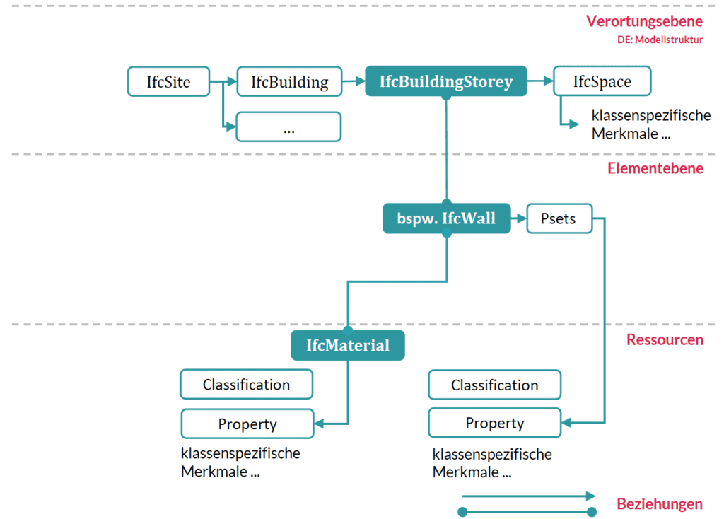
The location defines the spatial structure of a building in IFC. This declares building sites, the buildings on them, the storeys within them and the rooms on a storey.
Buildings are represented by elements (subclasses of IfcElement): e.g. walls, ceilings, columns, doors or windows. Each element (element instance) is given a unique identifier (GUID). The BIM application generates this unique declaration. Each element is optimized for mapping its functional area. For this purpose, it carries a standardized basic set of characteristics to describe relevant properties and their typical geometry. The properties are organized in groups (so-called Psets = property sets). Each element class has a typical Pset that contains the most important features. This Pset is designated with the suffix “Common” – e.g. Pset_WallCommon or Pset_DoorCommon. Psets can also apply to several element classes at the same time – e.g. Pset_Warranty. All functional elements are linked to storeys and therefore also belong to a building. In addition to the location, the elements and properties(property / property set), the IFC data structure also contains material information for declaring material-related properties.
bSDD platform
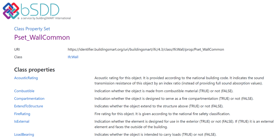
bSDD is an abbreviation for buildingSMART Data Dictionary(Link). It is a web-based service for the creation and use of DataDictionaries. A DataDictionaryis a collection of term definitions and the relationships between them. This allows objects and their attributes, permitted values, materials etc. to be defined. The relationships between the individual terms allow individual classification systems, ontologies, data structures, etc. to be created. buildingSMART publishes the IFC data schema as a DataDictionary in thebSDD, for example. It contains the IFC classes, standardized characteristics and property sets as well as the hierarchy and relationships between the individual term definitions (see Fig. 2.10).
The bSDD serves as a central, publicly accessible platform for DataDictionaries. This makes it possible to link content from different DataDictionaries. As a result, project partners working in different classification systems can easily translate terms to the other system and improve collaboration. In addition, the reference to existing terms enables a consistent and transparent interpretation of data, avoiding duplicated terms. The associated possibility of organizing multilingualism is also seen as an advantage of bSDD.
In addition to the publication of data, the bSDD serves as a source for the automated processing of data. Manufacturers can integrate the bSDD into their software and access the data. This allows models to be extended with information from the bSDD. If, for example, a wall is also assigned an individual class from the bSDD, the characteristics and permitted values from this class can be automatically adopted.
Each content stored in the bSDD is owned by the person/institution that created (declared) it. Other persons/institutions can add their respective translations to such a declaration. The bSDD is not a standard, but is owned by buildingSMART. It is based on the open IFD standard (International Framework for Dictionaries) of ISO 12006-3.
One example of content published in the bSDD in early 2024 is the dataholz Dictionary(link) from Holzforschung Austria. All superstructure definitions of tested and certified superstructures for roofs, walls and ceilings on the dataholz.eu platform are available in machine-readable and human-readable form.
IDM methodology
A data exchange of models and model information between organizational units requires technically precisely defined descriptions, terminology and interfaces. The IDM methodology (Information Delivery Manual) supports the description of information requirements in connection with the processes within the life cycle ( use cases). IDMs were developed by buildingSMART(link) and certified as an ISO standard (ISO 29481-1 and -2). These standards harmonize the creation and structuring of use cases.
IDMs are created using BPMN, the so-called process modeling. buildingSMART provides templates for the creation of IDMs(link).
Stakeholders along the value chain of a building use IDM to describe their information requirements. The following questions should be answered:
- Who are the roles involved and what are their interests?
- What model information is required?
- What additional inputs are required?
- What does the originator supply and what is required by the recipient?
The result is a document consisting of an interaction plan/transaction diagram and/or a process diagram as well as exchange information requirements AIA (EIR). The interaction plan defines the roles involved and their transactions. The process diagram supplements this with a chronological sequence of activities. In accordance with ISO 29481-1, each IDM component (interaction plan, process diagram, exchange information requirements) requires administrative data (header data) and a brief description of the content, use case, objective and scope of the component.
An IDM therefore defines the scope and type of an information request that is required or must be delivered by dedicated BIM organizational units (roles) at a specific point in time (process) (exchange requirements). The description of an efficient exchange in the form of an IDM is very important, as the transmitted relevant data must be communicated in such a way that the receiving software can also interpret it correctly.
ISO 29481-2 defines IDM zones from the perspective of user requirements and the technical solution (see Fig. 2.11).
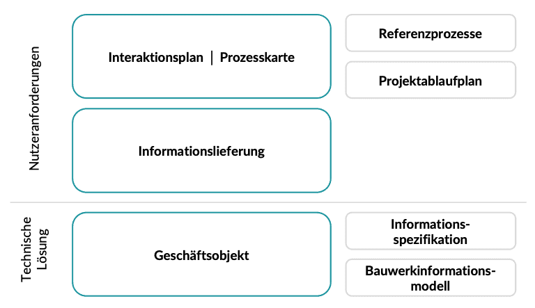
In the interaction between the individual ISO and buildingSMART standards, the IDM takes on the task of correctly describing the defined processes for an MVD or IDS using the bSDD and thus making them applicable.
For Germany, VDI 2552 Sheet 4 provides the following basic procedure for creating an IDM:
- Definition of roles and tasks
- Definition of recurring processes
- Determination of required information
- Determination of the information to be exchanged
- Mapping the information to be exchanged in the data model
- Creation of the corresponding model view (Model View Definition – MVD)
UCM platform
UCM(Use Case Management) is a platform(link) from buildingSMART for the public provision ofuse cases, their processes and requirements that have been developed in accordance with the IDM methodology. It shows best practices of use cases that can be adopted by other users in their projects. Users benefit from processes and requirements that have already been developed and have proven themselves in practice for a specific area.
In addition to a general description, UCM entries according to IDM contain a process map and process description as well as information requirements (e.g. required properties). This means that all contained use cases use a uniform structure and common language, regardless of the phase for which a use case was developed. The defined information requirements form the basis for the translation into specific technical requirements for BIM models. Depending on the type of requirement, these can be formulated as MVD or IDS.
MVD concept
The processes and information defined in an IDM are translated into specific technical requirements (machine-readable) in so-called MVD (Model View Definition)(link). They represent a process-related subset of the entire IFC schema. The IFC schema defines classes for a wide variety of objects and concepts in the construction industry that are required for different use cases. A classic use case is design coordination between the areas of architecture, structural analysis and building services engineering (MEP, FM handover). This coordination requires classes for objects from all three disciplines (e.g. walls, columns, pipes). Classes for the description of actions on the supporting structure, on the other hand, are not necessary. Furthermore, IFC offers various options (classes) for mapping geometry, e.g. only as a surface or according to the creation (extrusion of a profile). Information about the surface of an object is sufficient for design coordination software. MVDs can define precisely such restrictions. They describe a data exchange for a specific use or a specific workflow (application-specific data exchange requirements) and concretize software requirements.
MVDs can
- be as wide as almost the entire schema (e.g. for archiving a project) or
- be as specific as a few object types and associated data (e.g. for pricing a façade system).
Within this framework, they provide instructions for all IFC expressions(entities, relationships, attributes and properties, property sets, set definitions, etc.).
An MVD can define an application-specific view for each project applicant and thus specify a subset or a filtered view of IFC, which filters a limited element or data set. This defines “what” and “how” should be transferred. Similar to IFC in XML, an MVD is machine-readable using mvdXML.
The documentation of an MVD makes it possible to repeat the exchange and offers consistency and predictability across a large number of projects and software platforms. As different MVDs also require different software implementations, clients should not develop their own MVDs, but instead refer to the official MVDs to be used in projects. BIM regulations (AIA (EIR) and BAP (BEP)) therefore refer to the MVD in the data formats to be used. The most common MVDs are:
IFC2x3 – Coordination View CV2.0: Spatial and physical components for design coordination between the areas of architecture, structural analysis and building services engineering (MEP, FM Handover).
IFC4 – Reference View RV: Simplified geometric and relational representation of spatial and physical components to reference model information for design coordination between architecture, structural engineering and building services engineering departments.
IFC4 – Design Transfer View DTV: Advanced geometric and relational representation of spatial and physical components to enable the transfer of model information from one tool to another. No “back and forth” transfer, but a more accurate one-way transfer of data and responsibility.
In conjunction with the other ISO and buildingSMART standards, the MVD enables the concrete application of the process specifications of an IDM using subsets of the IFC data structure to transport the required data using the bSDD.
IDS format
Another option for the technical specification of information requirements from use cases is IDS (Information Delivery Specification). IDS is a new standard from buildingSMART for the computer-interpretable definition of exchange information requirements. The difference to MVD is that IDS concentrates on alphanumeric requirements. An MVD plays a role above all in software development to ensure that the classes required for geometry processing, localization or property assignment, for example, can be processed in the software. With regard to alphanumeric properties, the MVD must therefore define that properties can be created and assigned. However, IDS can specify which properties with which content (values and units) should ultimately be assigned to which objects in a project. It is therefore perfectly suited to defining the alphanumeric information content (level of information – LOI) in a project.
Traditionally, the LOI is often provided in Excel spreadsheets and PDF files. With IDS, there is now a standardized, computer-interpretable format for integrating this information into the automated BIM process. This can happen in two places:
- As a configuration file for authoring software to automatically create the required information structure, and
- as a configuration file for inspection software to automatically fill in inspection rules.
This closes the information flow between the definition and testing of model content.
IDS also offers new possibilities for defining model requirements more specifically. Until now, alphanumeric information was usually specified at class level (e.g. properties required for IfcWall). With IDS, requirements can also be made dependent on specific attributes, properties, external classes, relationships and materials. For example, a concrete quality property is only required if the material of an object is concrete. Or the FireRating values of a wall may only begin with “R” if it is load-bearing (e.g. REI90). This corresponds to a specific filtering of the affected elements and allows users to define their requirements more precisely.
Technically speaking, IDS corresponds to an XML file with a schema specified by buildingSMART. Thanks to this open, simple schema, IDS can be easily interpreted by computers and humans. It helps to define information requirements precisely and, in combination with other buildingSMART standards (bSDD and UCM), ensures unambiguity and clarity.
Software certification and IFC validation service
IFC is integrated in all common BIM applications. The software certification(link) by buildingSMART International ensures consistently high transfer quality. The software certification of buildingSMART is currently undergoing a change. Certification is currently being carried out for Model View Definitions (technical implementations of use cases) officially defined by buildingSMART. This MVD-based software certification is a paid service provided by buildingSMART that can be used by software manufacturers. This ensures that certified software can produce and process IFC files in accordance with these very general use cases.
A new, publicly accessible option for checking the quality of IFC files from any software is the buildingSMART Validation Service(link). IFC files can be uploaded to this platform to check their form. First and foremost, the Validation Service checks the conformity of an IFC file with the IFC standard. This involves checking the syntax (STEP Physical File), the IFC schema used (e.g. IFC4) and other rules of the IFC specification (e.g. a polyline must not contain any duplicated points). In addition to conformity with the IFC standard, conformity with referenced classifications from the bSDD can be checked if available in the IFC file. Fig. 2.12 shows the user interface of the Validation Service including the test results of a test model from Archicad. This model is publicly accessible on the TU Wien Research Data platform(link). Apart from content from the bSDD, the Validation Service does not check the actual content of an IFC file, such as the presence of special properties. Likewise, it cannot check IFC files against IDS requirements. The Validation Service is used for the technical validation of an IFC file, not the content.
Software manufacturers can use the Validation Service to validate their IFC implementation (currently limited to exported IFC files). For IFC users, the Validation Service makes it possible to check the quality of IFC files received. Overall, this can improve the technical quality of IFC files and thus also increase interoperability between different BIM applications.
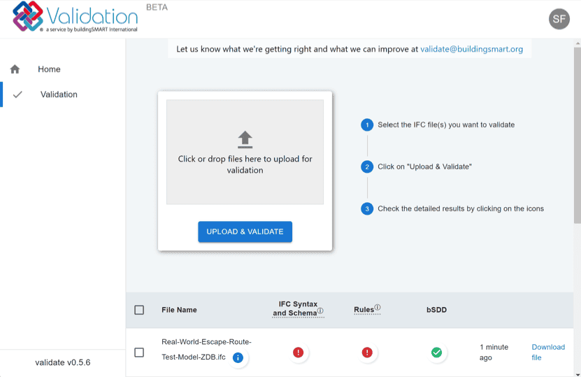
In future, this system will be used for the official software certification of buildingSMART. The Validation Service is currently available as a beta version and can be used by anyone with a free buildingSMART account.
BCF Comments
BCF stands for BIM Collaboration Format and is an open data format for model-based communication. Introduced in 2009 by the companies Solibri Inc. and Tekla Corporation, it was subsequently adopted by buildingSMART International as part of the openBIM standard(link).
BCF is used for the simplified exchange of information during the work process between different software products (based on the IFC exchange format) and thus the traceable communication of comments(issues) or changes. The current version BCF 3.0 enables the transfer of
- model-related comments(issues),
- the affected elements in the model (via the object GUIDs) and
- reproducible screen sections
as XML-formatted data between different BIM applications. This model-based communication improves coordination. Information about problems in the model (problem report and status), their location, viewing direction, component, comments, user, time or even changes in the IFC data model can be exchanged in a targeted manner. The aim is to transfer the marked information and not the entire model. An expansion of the range of functions for transferring properties between models is planned for future versions.
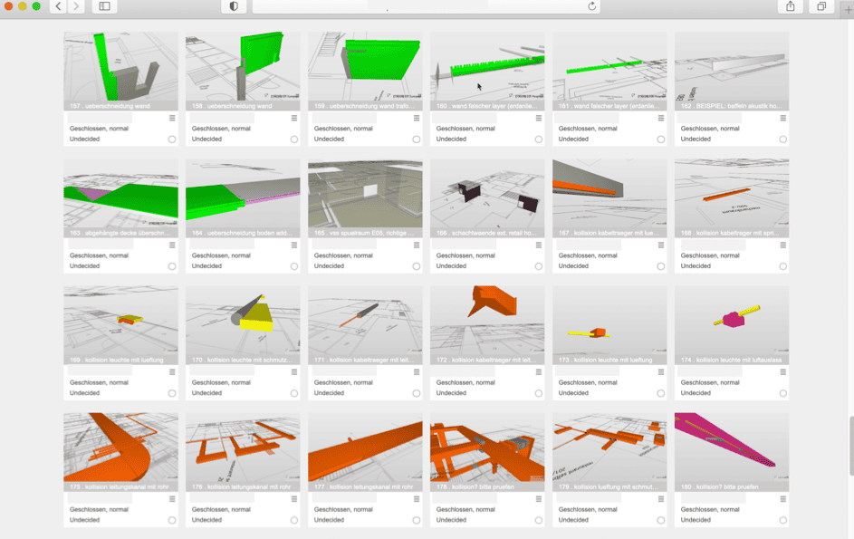
BCF is integrated in all common BIM applications. In some cases, special additional modules (add-ons) are also required to extend the range of functions.
DataSheets
DataSheets is a symbolic term for digital construction products. It is a container-based technology for digitally mapping the interaction of harmonized European product standards (CPR – Construction Products Regulation) and environmental product declarations, which ISO 23386 has been regulating since 2020.
The structure, composition and content of the DataSheets in various construction product structures is based on the specifications of the harmonized product standards. This conformity is essential, as all industry approval processes are based on these specifications and this is the only way to guarantee the completeness of the information in DataSheets for productive use. In addition, the integration of sustainability information (EPD – Environmental Product Declaration) of a construction product in accordance with ISO 22057 is planned in DataSheets .
A general distinction is made between generic (product-neutral) DataTemplates and specific (product-related) DataSheets . This makes it possible to use processes that comply with procurement law. In the planning stage, generic data templates can be used to precisely describe the requirements for materials or products, which can be clearly interpreted by a bidder in the course of the tender and responded to with specific DataSheets containing details of specific products. The processing of this information can be largely automated, as DataSheets are fully machine-readable. This advantage, in combination with the automated collection of masses and quantities from the digital models, will change the interaction between planning, execution, industry and logistics – enabling the end-to-end data chain for construction products.
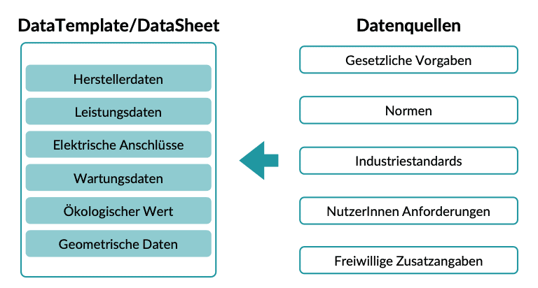
The interaction between DataTemplates/DataSheets and IFC-based digital models is regulated in ISO 23387. This refers to the bSDD when declaring the characteristics of a DataTemplate/DataSheet . This ensures that features of different products are coordinated and not created redundantly. The transfer of a DataTemplate/DataSheettogether with its bSDD-based features is possible file-based (using an IFC file) or web service-based (using an API connection). This development is very recent, so the integration of DataTemplates/DataSheets in BIM applications is still in preparation.
Publication from Eichler, C.C., Schranz, Ch., Krischmann, T., Urban, H., Hopferwieser, M., Fischer, S.: BIMcertHandbuch- Grundlagenwissen openBIM. Issue 2024. Mironde-Verlag, Niederfrohna, 2024. DOI: 10.34726/5384
URL: https://repositum.tuwien.at/bitstream/20.500.12708/192612/3/Eichler-2024-BIMcert %20Handbuch%20basic-knowledge%20openBIM-vor.pdf
Status: 23.01.2024
